
POWER CONTROL MODULES FOR ELECRONIC ACTUATORS SERIES, PART THREE
Edited by David Stockwell; Technical information provided by Roland Mueller & Simon Benik
Fundamentals of Pulse Width Modulation Exploring the effects of INDUCTANCE, FREQUENCY AND INPUT CURRENT RIPPLE relating to On-Off Electromagnetic Devices.
Pulse Width Modulation, Theory of Operation, Effects of INDUCTANCE, FREQUENCY & INPUT CURRENT RIPPLE:
To this point in this series of articles about powering electromagnetic devices with PWM circuitry, we have concluded that Duty Cycle and Inductance alone do not explain everything relating to the function of PWM circuitry.
This article will provide the rest-of-the-story, focusing on the effects of Inductance, the Frequency at which the voltage is pulsed on-and-off, and the impact this Frequency has on electromagnetic devices.
Herein also resides the design philosophy behind Magnet-Schultz of America’s family of Power Control Modules that can enhance the performance of all electromagnetic actuators.
GRAPH 4 (below) depicts a PWM Driver operating at a 10% Duty Cycle, at 1 Hz frequency:
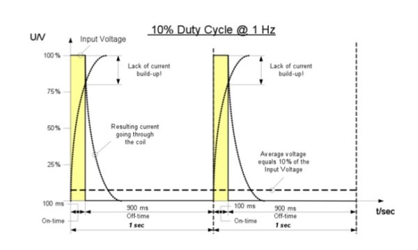
GRAPH 4
As one can see, due to the Inductance effect and the 1 Hz frequency voltage pulse, the current does not have sufficient time to fully rise, and also begins to drop well before reaching the 100% level. This Inductance induced short-fall remains constant, regardless of changes that are made to the Duty Cycle, as demonstrated in the next few examples.
In the example depicted in GRAPH 5, we utilize the same coil that provided the data found in GRAPH 3 (from article 2 of the PWM BLOG series, where the Duty Cycle is 50% and Frequency is 1 Hz), and in GRAPH 4 (from this article, part 3 of the PWM BLOG series, where the Duty Cycle is 10% and the Frequency is 1 Hz).
GRAPH 5 represents what happens when the frequency of the voltage pulse is increased to from 1Hz to 5Hz. Just as in GRAPH 2, the Average voltage still drops to 50% of the Input voltage, the input current does not fully rise, and the input current experiences a delay when in decay.
The new event to observe in GRAPH 5, however, is yet another Inductance effect related to the falling current.
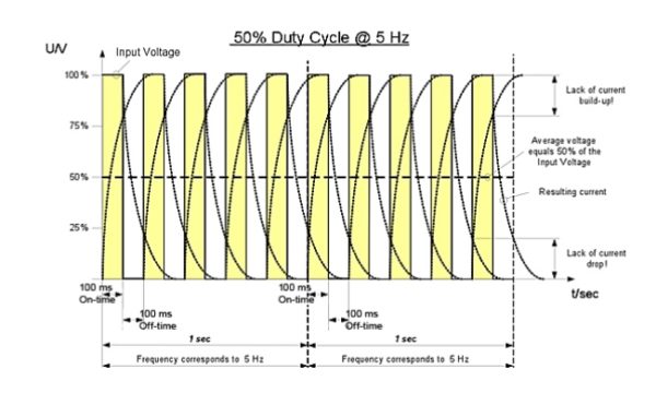
GRAPH 5
At the higher 5Hz input frequency, not only does the Inductance Effect prevent the current from fully rising, it also does not allow the declining current sufficient time to completely fall to zero. Because the higher input frequency prevents the input current from making a “full swing”, the current oscillates in a smaller window between 0% and 100%.
To help bring more clarity to this discussion, Graph 6 isolates the “resulting” current curve:
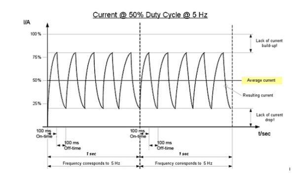
GRAPH 6
At 50% Duty Cycle and 5 Hz frequency, the “resulting” current oscillates between 20% and 80%. The magnitude of this oscillation is called the “RIPPLE” of the input current. Increasing the frequency will continue to narrow this window of oscillation, thereby further reducing the input current Ripple.
This begs the question, why is Ripple important?
If the current ripple is not significantly reduced, electromagnetic actuators will audibly “buzz”. This is especially true when the system includes a return mechanism, such as a spring. Buzzing occurs because the current ripple causes the plunger to oscillate back-and-forth. Movement in one direction is initiated by the magnetic field from the coil, and in the opposite direction it is aided by the return spring. This movement causes the plunger to impact the stop at the frequency imposed by the ripple current. Not only can buzzing become a disturbing noise, it can also lead to premature mechanical failure of the actuator.
Buzzing can be eliminated by significantly increasing the operating frequency. This frequency effect is demonstrated in GRAPHS 7 & 8 (where frequency is increased from 5 Hz to 10 Hz, while the Duty Cycle remains at 50%).
GRAPH 7 shows the complete rise-and-fall of the current curve, involving a PWM circuit operating a solenoid at 50% Duty Cycle, and 10Hz frequency.
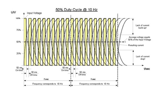
GRAPH 7
GRAPH 8 includes the same data as GRAPH 7, but, for clarity, eliminates all but the “resulting” current curve.
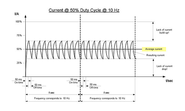
GRAPH 8
NOTE: As predicted, the higher 10 Hz frequency reduced the window within which the “resulting” current curve oscillates to 35% to 65% (compared to 20% and 80% @ 5Hz).
Interestingly, the average current, around which the ripple current oscillates, remains the same, further establishing that higher frequencies:
a. Have no impact on the Duty Cycle, hence the average output current, yet…
b. Reduce the ripple, improving the quality of the current.
Taken to the next logical conclusion:
c. Increasing the frequency of the voltage pulse to an extremely high level, will cause the rise and fall time of the current to become “out cycled”, meaning, the current ripple will be reduced to a point where the high inertia of the solenoid’s plunger/spring system will simply unable to synchronously move with the imposed current ripple frequency, therefore,
d. The solenoid should react as if it were being energized by Direct Current (DC), totally eliminating any audible buzzing.
GRAPHS 9 and 10 illustrate this ultra-high frequency prediction. The frequency of the voltage pulses in this scenario has been set at 20 KHz (2,000 times faster than the previous 10 Hz example). At 20 KHz, the current ripple disappears from GRAPHS 9 & 10, and one would expect that the resulting buzzing would become unnoticeable. Therefore, as postulated above, the solenoid would perform as if it were being powered by continuous DC voltage.
NOTE: The following graphs are not in proportion, rather, they are simply meant to depict the principle.
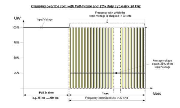
GRAPH 9
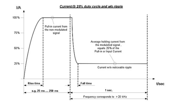
GRAPH 10
NOTE: The Average holding current is 25% of the Max voltage, commensurate with the 25% Duty Cycle, yet, the ripple current is undetectable.
This example demonstrates the philosophy Magnet-Schultz of America used to design the first member of our new Power Control Module (PCM) family, utilizing the principle of Pulse Width Modulation (PWM).
All of MSA’s PCM designs will employ sufficiently high frequencies that will reduce the current ripple effect to a point where the oscillating frequency of the plunger will be well above the audible hearing range for humans.
If you have further questions about this technology, or MSA’s family of PCM products, please do not hesitate to contact us at 630-789-0600.
This ends the preliminary discussion involving PWM modules for use with on-off electromagnetic devices.
In future BLOGS, please look forward to topics involving PCMs for use in:
- Current Controlled applications,
- Proportional driving schemes, (where, despite what was explained above, current ripple (hence DITHER) could be beneficial toward dealing with STICTION, Wide Input Voltage scenarios, where PWM circuits can stabilize the input voltage to enable solenoids to effectively operate over wide voltage ranges (i.e. automotive applications where voltage can vary from 9 to 16 Volts), Proportional, Dual Coil applications, LVDT driving schemes, Voice Coil driving schemes.
As a leading manufacturer of standard, specialty and custom Electromagnetic devices—Electromechanical and Electrohydraulic—MSA’s advanced engineering, innovative design and lean manufacturing capabilities enable our customer’s products to outperform their competition. Learn how we can help you with your next project.


Leave A Comment