
POWER CONTROL MODULES FOR ELECTROMAGNETIC ACTUATORS: PART TWO
Edited by David Stockwell; Technical information provided by Roland Mueller & Simon Benik
Fundamentals of Pulse Width Modulation, including effects of DUTY CYCLE and INDUCTANCE relating to On-Off Electromagnetic Devices.
Pulse Width Modulation (PWM) is a fully electronic power control circuit which, when applied to electromagnetic actuators, can provide superior actuation force at max air-gap, then automatically lower the power at zero air-gap so as to overcome the constraints involving excessive HEAT, eliminate the worries related to Coil Duty, reduce energy consumption, and enable the use of physically smaller electromagnetic devices.
In the second part of this three-part BLOG series, we will begin the discussion relating to the fundamentals of how PWM provides power to On-Off style electromagnetic actuators.
PWM DERIVATION OF THE TERM:
- PULSE refers to the burst(s) of energy (current) that are applied to the coil of the electromagnetic device by the PWM circuitry.
- WIDTH refers to the percentage of time the current PULSE is “on”.
- MODULATION refers to the frequency at which the current PULSE is turned on-and-off.
PWM THEORY OF OPERATION DUTY CYCLE:
PWM circuitry varies the on-time and the off-time of a SQUARE WAVE signal, at a fixed frequency. This signal energizes the coil of an electromagnetic actuator.
The ratio of on-time vs. off-time [ton / (ton + toff)] is called DUTY CYCLE. Changing this ratio (changing the DUTY CYCLE) generates an average output voltage which, in turn, becomes the input voltage for the actuator.
Duty Cycle can be adjusted from 0% to 100%. Although, since 0% Duty Cycle is an unlikely case, thus will be eliminated from this discussion.
100% Duty Cycle is required when one desires to actuate (pull-in) a solenoid plunger at maximum air-gap. The application of 100% input voltage to a solenoid coil for a very specific, but short period of time, is necessary to generate the highest possible Actuation force when the solenoid is at its “weakest point” (at maximum “air-gap”).
Once Actuation has occurred, the subsequent reduction of the Duty Cycle to a level lower than the 100% is made by the PWM circuitry. Based on the percentage of this imposed Duty Cycle, a specific Average Voltage output is generated, so that different power levels can be achieved.
This Average Output Voltage develops a corresponding level of magnetic attraction, creating sufficient HOLD force to keep the solenoid plunger at zero “air-gap”.
Herein lies the PWM circuit’s ability to reduce energy consumption, and avoid excessive heat.
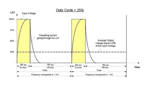
GRAPH 1 depicts a PWM Driver operating at a 25% Duty Cycle:
NOTE: Because of the 25% on, 75% off timing sequence, the Average Output Voltage is 25% of the initial input voltage.
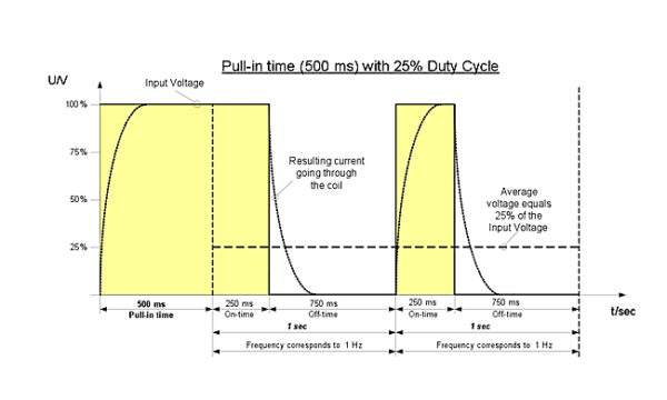
GRAPH 2 demonstrates a PWM Driver operating at a 25% Duty Cycle, with extended pull-in time of 500 ms for the first pulse, to ensure that the plunger fully seats against the stop:
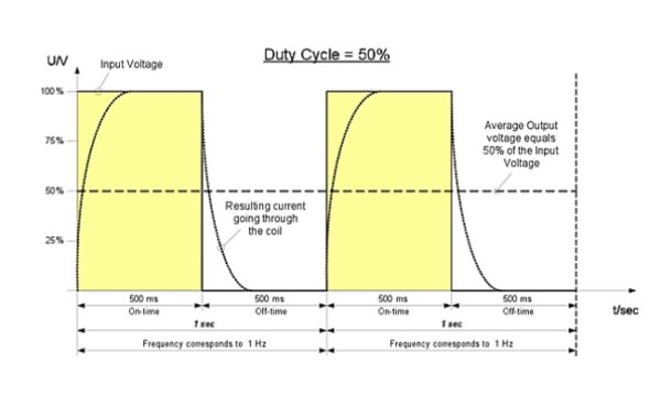
GRAPH 3 depicts a PWM Driver operating at a 50% Duty Cycle:
NOTE: In the 50% Duty Cycle scenario depicted in GRAPH 3, the 50%–on–50%-off timing sequence creates an Average Output Voltage which is 50% of the Input voltage.
This definition holds for every Duty Cycle scenario, meaning, the Duty Cycle percentage defines the Input Voltage:
- 10% Duty Cycle suggests that the input voltage will be 10% of the Average output voltage of the PWM circuitry.
- 25% Duty Cycle suggests that the input voltage will be 25% of the Average output voltage of the PWM circuitry.
- 50% Duty Cycle suggests that the input voltage will be 50% of the Average output voltage of the PWM circuitry.
PWM THEORY OF OPERATION, THE INDUCTANCE EFFECT:
Duty Cycle is only part of the story relating to how PWM circuits work.
Upon closer examination, note that all current curves shown in the above graphs depict a delay in both the “rise” and the “fall” of the current pulse, as the power is switched on-and-off.
This delayed reaction suggests that there is more going on than just the measured (omic) resistance within the coil. Some other form of “resistance” is effecting a delay in both the rise and fall of the current.
This additional resistance effect is caused by INDUCTANCE. Inductance is a characteristic that is present in all electromagnetic actuators, and is influenced by:
- The materials and geometry of the coil, including: The cross section of the coil, magnet wire size, and number of turns (the number of times the magnet wire is wound around the body of the coil).As well as by,
- The Magnetic Permeability of the device: Here, permeability is a measure of the ability of magnetic flux to freely flow through the materials that comprise the structure of electromagnetic actuators (in a solenoid, these materials would be the Frame, Stop and Plunger).Of further interest regarding permeability is the fact that the overall Inductance of the electromagnetic device varies throughout the range of movement of the plunger.
To completely understand and describe PWM functionality, it is important to understand that as a coil is energized with voltage pulses from a PWM circuit, operating at a specific frequency, the Inductance of the whole system plays a significant role in the rise-and-fall delays involving the input current. However, there is far more to this than first meets the eye.
The rest-of-the-story concerning the theory of operation, and an in-depth look into the effects of Inductance, the Frequency at which the voltage is turned off-and-on, the impact that this frequency has on the input current, and on the operation of electromagnetic devices utilizing PWM circuitry, is covered in part three of this BLOG series.
As a leading manufacturer of standard, specialty and custom Electromagnetic devices—Electromechanical and Electrohydraulic—MSA’s advanced engineering, innovative design and lean manufacturing capabilities enable our customer’s products to outperform their competition. Learn how we can help you with your next project.


Leave A Comment