HIGH SECURITY, ROBUST LOCKING APPLICATIONS, BALL-DETENT LOCKING SOLENOIDS: PART ONE
Edited by David Stockwell; Technical information provided by Roland Mueller & Simon Benik
The need often arises to find a device that can securely lock the door to a room, the door or drawers of a cabinet, or even to securely hold independent sections of a mechanical apparatus together while the system is operational. The wish list for such a device might also include:
- Compact size, yet able to withstand rigorous attempts to forcefully unlock/separate the locked entity.
- Scalable dimensions, which can easily be adapted to meet varying mechanical demands.
- Designs which do not require excessive electrical power to provide a high locking/unlocking functionality.
- Operating modes suited to FAIL-SAFE (meaning, the device automatically unlocks if power is lost), or FAIL-SECURE (meaning, the device remains locked if power is lost) applications.
A unique approach to meeting all of these demands, and more, is a device that blends the locking power of Ball-Detent technology, with the linear motion of a solenoid. Two design approaches, both of which are available in either a FAIL-SAFE or a FAIL-SECURE format, are the first two members of a new family of such devices:
- The Independent Locking-Receptacle, Ball-Detent Locking (BDL) Solenoid and,
- The Integrated Locking Receptacle, Ball-Detent Locking (BDL) Solenoid
This first BLOG in this new series will focus on the Independent Locking-Receptacle, BDL-Solenoid. BLOG two of the series will discuss the Integrated Locking-Receptacle variant. Subsequent BLOGS will present additional concepts as they are developed.
INDEPENDENT LOCKING-RECEPTACLE, BDL-SOLENOID
A FAIL-SAFE version of the Independent Locking-Receptacle Solenoid is depicted in Figures 1 and 2, in the de-energized, unlocked state.
In Figure 1, the solenoid assembly is shown not yet inserted into the Independent Locking-Receptacle. Because the device is de-energized, the Locking-Balls are free to move radially inward, toward the hollow core of the Ball-Housing, rendering the device unlocked.
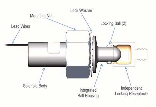
FIGURE 1
FIGURE 2 depicts the Ball-Housing/Solenoid assembly being inserted into the Locking-Receptacle. Again, because the solenoid is de-energized, the Locking Balls are free to move radially inward, allowing the assembly to easily pass by the Retaining Lip of the Locking-Receptacle.
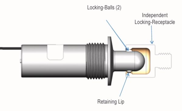
FIGURE 2
Figure 3 depicts an energized, FAIL-SAFE version of this solenoid assembly, which is fully inserted into the Locking-Receptacle. Because it is energized, the Locking-Balls are not allowed to move radially inward, which prevents the assembly from being withdrawn past the Retaining Lip, and renders the mechanism locked.
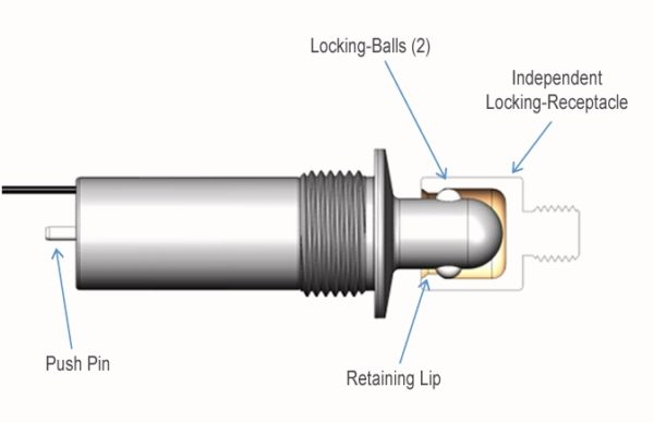
FIGURE 3
A FAIL-SECURE variant of this solenoid assembly will respond opposite to what was described above.
When de-energized, the Locking-Balls will be prevented from moving radially inward, keeping the Solenoid from passing by the Retaining Lip of the Independent Locking-Receptacle. This condition will “lock” the solenoid assembly either inside, or outside of the Receptacle.
When energized, the Locking-Balls will be free to move inward, unlocking the device, allowing the solenoid assembly to easily move both into and out of the Receptacle.
KEY FEATURES OF THE INDEPENDENT LOCKING RECEPTACLE, BDL SOLENOID
FAIL-SAFE or FAIL-SECURE Operation
In either operating mode, the relevant functionality is achieved by adding or removing electrical power (either intentionally, or unintentionally) from the solenoid coil.
Self-Contained, Moisture and Dust Resistant Mechanism
The self-contained nature of the Integrated Ball-Housing and Locking-Balls, coupled with internal O-rings, serve to minimize ingression of moisture, dust and other foreign matter.
Locking/Holding Forces
The locking/hold force is dependent upon the size and material of the Locking-Balls, and the size, design and material of the Locking-Receptacle. The locking/hold force of an existing design exceeds 500 pounds.
Durability (the number of locking/unlocking cycles the device can withstand, without failure)
Testing with an existing design has proven that the Ball-Housing, Locking-Balls, and Locking-Receptacle, coupled with unique design features of the internal components, can provide in excess of 1 million locking-unlocking events.
Push Pin
The push pin can be used to manually unlock, or to lock the device (depending on whether it is a FAIL-SAFE, or a FAIL-SECURE design.
Energy Required to Lock
The electrical energy required to perform the locking or unlocking function is dependent upon the design and size of the solenoid coil and internal components, the force of the return spring or return mechanism, and the stroke necessary to accommodate the desired Locking-Ball and Locking-Receptacle dimensions.
The electrical power required for an existing design is as follows:
Actuation energy: 96 watts @12 VDC (applied for 100 ms, to actuate the solenoid), and
Holding energy: 5.6 watts @12 VDC (applied continuously, to keep the solenoid actuated).
These power levels can be modified to suit the design characteristics demanded of, and the power available in, each application.
Size
The external dimensions of an existing design, depicted in FIGURE 4, are as follows:
Solenoid/Ball-Housing Assembly:
– Solenoid body diameter: 1”
– Length of Device (from the back of the Solenoid to the tip of the Ball-Housing): 3.8”
Ball-Housing:
– Tip Diameter: .625”
– Mounting Thread: 1-1/8-UNF
Independent Locking Receptacle:
– Outer Diameter: .8”
– Length: .9”
– Mounting Thread: 3/4-18 UNS
Again, the size of the BDL-Solenoid assembly is fully scalable in order to meet the unique locking force, stroke and electrical requirements of any application.
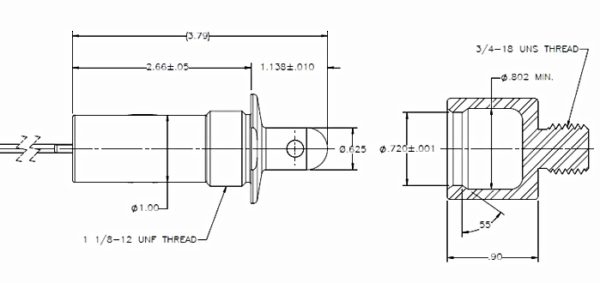
FIGURE 4
Energy Saving Option
For those who wish not to continuously apply power in order to maintain the locked or the unlocked condition (for either a FAIL-SAFE or a FAIL-SECURE format), a Permanent-Magnet can be incorporated into the body of the solenoid.
The attractive “pull-force” that is created by the permanent-magnet will hold the solenoid’s internal components in the appropriate position, against the force of an internal spring, thereby maintaining the relevant locked, or unlocked state.
This Permanent-Magnet design requires that only a momentary pulse of energy be applied to the solenoid’s coil, in order to actuate the assembly.
Applying a subsequent pulse of reverse polarity to the coil will nullify the hold force of the Permanent-Magnet, allowing the internal spring to return the solenoid’s components to the position where they will either inhibit, or allow free movement of the Locking-Balls (depending on whether the base design is either FAIL-SAFE or FAIL-SECURE).
The pulse of energy needed to either actuate, or deactivate the solenoid can come directly from a small DC power supply, from a battery, or from an appropriately sized capacitor within a capacitive discharge circuit.
NOTE:
When choosing this Energy Saving Option, the device will no longer automatically function in either a FAIL-SAFE. or a FAIL-SECURE mode, because a pulse of energy must be applied to the coil before the system will change state.
This completes the introduction of the Independent Locking Receptacle, Ball-Detent Locking Solenoid. If you think that such a solenoid might be the perfect fit for your application, please contact Magnet-Schultz of America. We would be happy to explore whatever is required to meet your system’s locking challenges.
MSA invites you to explore BLOG 2 of this series to learn about the function and capabilities relating to the FAIL-SECURE variant of the BDL-Solenoid design.
As a leading manufacturer of standard, specialty and custom Electromagnetic devices—Electromechanical and Electrohydraulic—MSA’s advanced engineering, innovative design and lean manufacturing capabilities enable our customer’s products to outperform their competition. Learn how we can help you with your next project.


Leave A Comment