
POWER CONTROL MODULES FOR ELECTROMAGNETIC ACTUATORS: PART ONE
Edited by David Stockwell; Technical information provided by Roland Mueller & Simon Benik
Magnet-Schultz of America (MSA) discuses how to achieve smaller, higher performing, more energy efficient solenoids, and avoid heat issues by utilizing electronic power control techniques, such as Pulse Width Modulation (PWM).
Driving electromagnetic actuators (such as solenoids) by utilizing the conventional approach of applying a constant voltage and current to the coil is an effective, but also an inefficient use of the energy consumed. The power required to get the solenoid’s plunger to move at the max stroke (max “air-gap”), simply becomes excessive when the plunger reaches the fully seated, zero stroke (zero “air-gap”) location.
Furthermore, the ever-present quest to achieve greater actuation forces from the smallest possible actuator package is befallen by excessive HEAT that is generated within the coil of such devices. The resulting elevated coil temperature increases the resistance of the coil, which derides the desired force at all strokes. Worse, HEAT also jeopardizes the mechanical integrity of the device (potentially melting magnet wire insulation, plastic bobbins and/or encapsulation materials, and destroying embedded electronic components).
So, how can one achieve smaller, higher performing, more energy efficient solenoids, yet avoid HEAT issues?
The answer is, by utilizing electronic power control techniques, such as Pulse Width Modulation (PWM).
Before engaging in a rigorous PWM discussion, the first article in this three-part BLOG series will provide a review of the “basics” involving the relationship between force, stroke, heat and input power as they relate to solenoids. To be sure, these relationships and characteristics also exist with other electromagnetic actuators.
FOUR BASIC COMPONENTS + A KEY DESIGN ELEMENT THAT COMPRISE A SOLENOID:
- The COIL: The component that generates the magnetic flux when energized,
- The stationary POLE PIECE (or, Stop): The component that magnetically attracts the plunger,
- The moving PLUNGER (or, Armature): Movement of the plunger provides the mechanical work,
- The FRAME: The magnetically permeable envelope surrounding the solenoid.
The AIR-GAP (or, Stroke): The space between the plunger and the stop, across which a magnetic differential is created.
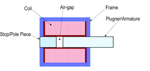
FIGURE 1: The AIR-GAP is a key design element
SOLENOID OPERATING CHARACTERISTICS:
Applying electrical energy to a solenoid coil generates an electromagnetic field, resulting in the flow of magnetic flux through the frame, plunger and stop. This flux induces a magnetic differential as it jumps the air-gap between the plunger and the stop.
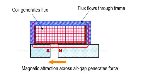
FIGURE 2 (ABOVE): Actuation force
The magnetic differential creates an attractive magnetic force between the stationary stop and the moveable plunger. This force, called the “ACTUATION” force, is inversely proportional to the square of the distance (the air-gap) between the plunger to the stop (F ~ 1/x^2), and serves to draw the plunger toward the stop.
This non-linear relationship, (see FIGURE 3 below) depicts the magnetic efficiency of the device. The magnetic efficiency dictates that the ACTUATION force (the Y-axis below) is the smallest when the air-gap (the X-axis below) is the largest, and largest when the plunger is fully seated against the stop (at zero air-gap). At this point, it is called the “HOLD” force.
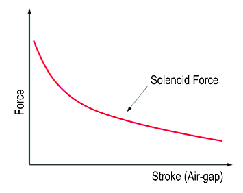
FIGURE 3 (ABOVE): Hold force
Because magnetic efficiency increases as the plunger moves toward zero air-gap, progressively less electrical energy is required to keep the plunger moving along this path, and far less energy is needed to “HOLD” the plunger at zero air-gap. For this reason, when utilizing a conventional driving scheme, where the applied energy is kept constant, the excess, wasted energy at zero air-gap is simply converted into HEAT.
THE RELATIONSHIP BETWEEN HIGHER ACTUATION FORCE, HEAT, SOLENOID SIZE AND COIL DUTY:
In the majority of applications, the main focus is to achieve the greatest Actuation force at max air-gap, especially when a return spring is embodied in the design. Unfortunately, with the conventional driving scheme, the resulting high HOLD force exceeds what is needed, thereby wastes energy.
Because of packaging constraints, and in order to make the complete system function as desired, it often becomes desirable to increase the ACTUATION force within a particular solenoid size. This can easily be accomplished by decreasing the resistance of the coil, thereby increasing both the current flow and the magnetic flux that is generated by the coil. However, passing progressively higher current through the coil will:
- Generate heat, which will
- Increase the resistance of the coil, which will
- Reduce the current that flows through the coil, which will
- Reduce the magnetic flux that can be generated by the coil, which, ultimately, will
- Reduce the force at all air-gaps produced by the actuator
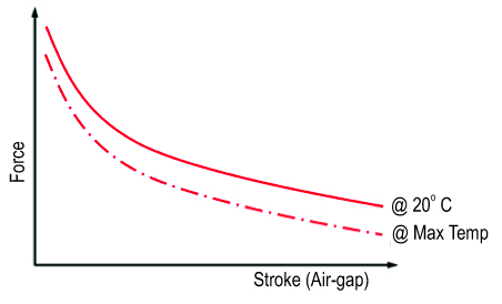
FIGURE 4 (ABOVE)
This conundrum means, unless the fixed voltage input (utilizing the conventional driving scheme) is manually adjusted to limit the “on-time” vs. the “off-time”, thereby enabling the coil the time needed to cool between successive power-on cycles, higher ACTUATION forces will not be consistently achieved, and the risk of heat related damage to the actuator becomes a very real possibility.
Herein a new definition, “Coil DUTY”, enters the discussion involving electromagnetic actuators.
In order to achieve the desired Actuation force from a given solenoid package, yet not exceed the operating limits of the device, the coil must be designed within one of three standard paradigms—
Continuous Duty Coil (CD):
For CD coils, the coil resistance is designed such that a given input power can be applied 100% of the time, enabling the coil to reach a thermal balance that will not generate excessive HEAT. The result is a device that provides the lowest potential Actuation force for a given package size, but can be energized indefinitely.
Intermittent Duty Coil (ID):
For ID coils, the coil resistance is designed to be much less than the CD scenario so that, when utilizing the same input power level as the CD coil, the resulting higher current will provide significantly higher actuation forces (at all strokes). However, the on-time cannot exceed 25%. 75% Off-time is required to enable the coil to reach a thermal balance that will not generate excessive HEAT. The graphic relationship between the CD and ID scenarios is depicted in Figure 5.
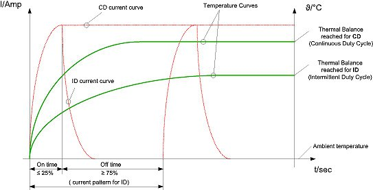
FIGURE 5 (ABOVE): Relationship between Power-On vs.-Off time, and Coil Temperature Rise, for Continuous Duty vs. Intermittent Duty Solenoids
Pulse Duty Coil (PD):
For PD solenoids, the coil resistance is designed such that the same input power level, as in the CD scenario, will provide the maximum possible actuation force (at all strokes) for a given size of solenoid. However, for PD coils, the on-time cannot exceed 10%. 90% off-time is required to enable the coil to reach a thermal balance that will not generate excessive HEAT.
ALTERNATIVES TO THE CONVENTIONAL, FIXED VOLTAGE APPROACH TO ACTUATE SOLENOIDS:
With this rudimentary understanding of how solenoids function, it brings us back to the original question:
What power control systems are available to help one achieve smaller, higher performing, more energy efficient solenoids, yet avoid HEAT issues?
An ideal power control system would:
- Generate the highest possible actuation force, to get the plunger moving at max air-gap, then
- Automatically reduce the applied energy to a sustaining level, capable of:
- Providing sufficient “hold” force at zero air-gap,
- Preventing over-heating, (thereby eliminating Coil Duty issues), and
- Providing the most efficient overall use of energy
The only way to achieve all of these goals is to employ an automatic, electronic power control circuit. One of the most basic of these circuits is called Pulse Width Modulation (PWM).
A full description of PWM for on-off solenoid applications is offered in part two of this BLOG series. Subsequent BLOGS will explore increasingly capable power control schemes, including proportional actuation, position control, and more.
We want to thank you for the time you have invested in learning about Power Control Modules for Electromagnetic Actuators, and encourage you to contact MSA with any questions you may have.
As a leading manufacturer of standard, specialty and custom Electromagnetic devices—Electromechanical and Electrohydraulic—MSA’s advanced engineering, innovative design and lean manufacturing capabilities enable our customer’s products to outperform their competition. Learn how we can help you with your next project.


Leave A Comment