
LINEAR MOTOR SERIES: PART TWO
Magnet-Schultz of America (MSA) reveals the design and manufacturing techniques, performance, and functional characteristics of a Linear Motor.
Edited by David Stockwell; Technical information provided by Dr. Jonathan Gamble & Kevin Code
DESIGN & MANUFACTURING TECHNIQUES
1. External Appearance: The Linear Motor (LM) assembly looks just like a conventional unidirectional electrohydraulic actuator. It includes a pressure tube, a removable coil, a coil nut and two external O-rings (one to help maintain friction between the retaining nut and coil, and one to help seal the tube-to-valve interface). See figures 1 and 2 below.
2. Internal Design & Manufacturing Techniques
a. Linear Motor Tube Assembly:
The precision machined LM tube utilizes MSA’s time proven in-fill brazing manufacturing process, enabling the tube to reliably provide working pressures up to 6,000 psi., while maintaining the durability needed to pass the NFPA standard fatigue test (consisting of pulses of hydraulic fluid at 1.2 times the working pressure, every 100+/- 10 milliseconds, for 1 million cycles).
Basic Differences Between the Linear Motor & Conventional Unidirectional Tube Assemblies:
Linear Motor Tube:
Figure 1 shows a cut-away view of the Linear Motor tube. Note, the in-filled braze ring, which functions as the air-gap, is located in the center of the LM tube. For a unidirectional tube, this ring would be at either end of the tube, depending on whether it is a push or pull design.
The LM Plunger:
Unlike the unidirectional plunger, which is a solid piece of steel, the LM plunger incorporates two permanent magnets, sandwiched between three steel discs.
Combined Effect of the Unique LM Tube & Plunger Design:
It is the centralized location of the braze ring and the presence of the permanent magnets that enable bi-directional operation for the LM.
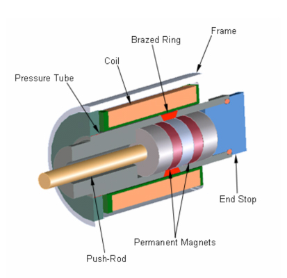
Figure 1: Linear Motor Tube Construction
b. Linear Motor Coil:
The LM coil, is identical to our conventional hydraulic coil design, thereby:
-
- Taking advantage of MSA’s proven history of high performance and demonstrated longevity of field service,
- Benefiting from the immediate availability of multiple connector variants, and
- Retaining existing certifications for water and dust ingression (which can range from IP-65 to IP-69, depending upon the integrated connector variant selected).
c. Linear Motor Tube & Coil Assembly:
The Linear Motor coil slips over the LM tube, just like a conventional unidirectional design.
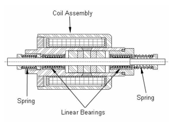
Figure 2: Linear Motor Tube and Coil Assembly
(also depicted are the Linear Bearings which are used to reduce sliding friction)
PERFORMANCE & FUNCTIONAL CHARACTERISTICS
a. Inductance & Actuation Speed:
The inductance of the LM and the variation of the inductance over the working stroke are substantially lower than other bi-directional actuator alternatives.
Coupled with the presence of the permanent magnets, which are imbedded in the LM plunger, and the patented manner in which these magnets participate in the bi-directional operation of the LM, faster actuation speeds can be achieved, making this device especially attractive for high-speed valve applications.
b. Force and Volumetric Efficiency:
Linear Motors provide a higher volumetric efficiency than a unidirectional electrohydraulic actuator, a conventional solenoid, and even a voice coil. This means they require less input power to achieve the same output force. Or, conversely, they can provide greater output force with the same input power relative to unidirectional tubes. This feature helps to maintain the traditional three-position, proportional valve functionality.
c. Stoke & Actuation Speed:
The typical stroke of conventional, unidirectional actuator tubes is 2mm (for 19mm diameter tubes), and 3mm (for 22 mm diameter tubes).
Because the length of the bi-directional LM is the same as the conventional tube, the LM design has been optimized for a working stroke of 1mm in each direction (for MSA’s 19mm diameter reference design LM tube) and 2mm in each direction (for MSA’s 22mm diameter reference design LM tube). Either of these reference designs can easily be scaled up or down, to precisely meet the requirements of any new LM application.
d. Interface with the Valve Spool:
The moving armature (plunger) assembly is connected to the valve via a non-magnetic push-rod (Figure 2).
Additional Information
If you happen to have missed PART ONE of this series, which covers Linear Motor Concept, Genesis of Development, Background, and Physical Characteristics, we invite you to check it out.
We also invite you to look for PART THREE, which concludes the series with topics covering LM’s Theory of Operation, Empirical Test Results, and Additional Development Work.
We want to thank you for the time you have invested in learning about Linear Motors, and we encourage you to contact MSA with any questions you may have relating to your electromagnetic actuator needs.
As a leading manufacturer of standard, specialty and custom Electromagnetic devices—Electromechanical and Electrohydraulic—MSA’s advanced engineering, innovative design and lean manufacturing capabilities enable our customer’s products to outperform their competition. Learn how we can help you with your next project.


Leave A Comment