
The latest entry in the Magnet-Schultz of America Solenoid 101 blog explains the basic concepts behind hydraulic solenoids. This primer will reduce the content to the simplest terms for a quick and clear understanding of the fundamental concepts. Check our blog history for information on more technical subjects and feel free to make suggestions for future posts.
What is a Hydraulic Solenoid?
At a basic level, a hydraulic solenoid functions similarly to a normal solenoid. An electromagnetically inductive coil is wound around a metal core which creates a magnetic field when an electric current passes through it. The magnetic field acts upon an armature and creates a mechanical force. The armature interfaces with a movable element in the final application that requires positioning. The primary differences between an electromechanical and hydraulic solenoid are the end function and construction.
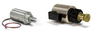
An Electromechanical Solenoid and a Hydraulic Solenoid
Hydraulic Solenoid Function
Hydraulic solenoids are primarily used in hydraulic pumps and valves. These solenoids can be designed to perform push, pull, or push/pull actuation functions with either proportional or on/off stroke characteristics.
Hydraulic Pumps
Hydraulic pumps convert mechanical energy into hydraulic energy. They create the flow and pressure of fluid in a hydraulic circuit. A hydraulic solenoid can be used in pumps like a Variable Displacement Axial Piston Pump to control the volume of the hydraulic fluid output. These pumps use pistons to control the fluid flow. The solenoid is used to position a swashplate, which adjusts the positioning of the pump’s pistons. The change in piston position changes the volume of space available in the piston cavity for fluid to flow through. The greater the space, the higher the pump’s displacement will be.
Hydraulic Valves
A hydraulic valve controls the flow of hydraulic fluid by opening, closing, or partially obstructing pathways. Solenoids can be used as actuators in valves designed to control the flow, limit system pressure, or control direction. The example below shows a Directional Control Valve that uses two coils to control the positioning of a spool. The spool is pushed or pulled into position, opening and closing channels to change flow direction and volume.
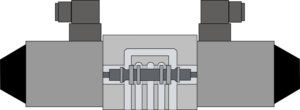
Cross Section of Directional Contol Valve
Hydraulic Solenoid Construction
A hydraulic solenoid has 2 basic design types. The first is the integrated design, which is the full solenoid unit as a single component. This offers the highest performance but requires the system to be depressurized when the solenoid needs to be replaced. The second is the removable coil design. This design has a separate tube which is installed directly into the application, and then the coil slides over the tube. A nut is used to secure the coil to the tube. This design allows for the coil to be replaced without also removing the tube from the application, so the application can remain pressurized.
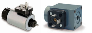
Removable Coil Design Hydraulic Solenoid and an Integrated Hydraulic Solenoid
Removable coil designs come in many different forms. The coils can be stamped, rolled, or cylindrical. Common tube designs include 3 piece brazed designs suited to on/off functions or an infilled brazed design that is suited to proportional functions. Keep an eye out for future blog posts that will describe the functional differences between these hydraulic coil design styles.
Magnet-Schultz of America specializes in the custom engineering and manufacturing of solenoids, solenoid valves, electromagnets, voice coils, hydraulic tubes and coils, and locking devices. If you have any questions related to sourcing or manufacturing, please contact us. We will be happy to assist in the development of your application. Browse past blogs for a more in-depth look at solenoid functions and subscribe to the notifications for future posts!

Leave A Comment