HIGH SECURITY, ROBUST LOCKING APPLICATIONS, BALL-DETENT LOCKING SOLENOIDS:
PART TWO
Edited by David Stockwell; Technical information provided by Roland Mueller & Simon Benik
BLOG 1 of this two-part series discussed the need for, and desired characteristics of a robust locking device, capable of providing a high hold force in a small package. It then went on to describe the capabilities of an Independent Locking-Receptacle, Ball-Detent Locking Solenoid for such applications.
BLOG 2 presents the Integrated Locking-Receptacle variant of the BDL-Solenoid, where the Locking-Receptacle is incorporated into the solenoid body and mechanism. To effect the locking function, this Locking-Receptacle must interface with an independent Ball-Shaft (Figure 1).
In FIGURE 1 (below), the Integrated Locking-Receptacle Solenoid assembly is depicted in the de-energized, FAIL-SECURE state, with the independent Ball-Shaft already inside the device.
The locking function is accomplished by virtue of the fact that, when this solenoid is de-energized, the outward radial movement of the Locking-Balls is constrained, keeping them pressed firmly against the “Ball” shaped portion of the Independent Ball-Shaft.
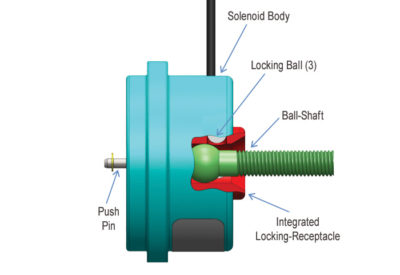
FIGURE 1
Unlocking the FAIL-SECURE Version of the Integrated Locking Receptacle, BDL-Solenoid
FIGURES 2, 3 and 4 depict an energized FAIL-SECURE, Integrated Locking-Receptacle Solenoid Assembly. As such, radial pressure is removed from the Locking-Balls, which effectively unlocks the device, enabling the Ball-Shaft to push them aside as it is withdrawn from the Locking-Receptacle (FIGURE 3).
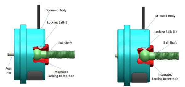
Figures 2 & 3
Initiating the Locking Process for the FAIL-SECURE, Integrated Locking Receptacle BDL-Solenoid
To initiate the locking procedure for the Fail-Secure version of this solenoid assembly, first, the solenoid must be energized. This will allow the Locking-Balls to be radially displaced by the Ball-Shaft as it is inserted into the Locking-Receptacle. Once fully seated in the Receptacle, energy can be removed from the solenoid coil. This action keeps the Locking-Balls from moving radially outward, preventing the Ball-Shaft from being withdrawn from the assembly, and effectively locking whatever is attached to the Ball-Shaft in place.
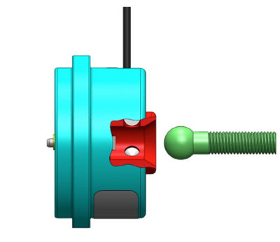
Figure 4
A FAIL-SAFE version of the Integrated Locking-Receptacle solenoid assembly will respond opposite to what was described above.
When de-energized, the Locking-Balls will be allowed to move radially outward, allowing the Ball-Shaft to be withdrawn from the solenoid assembly, and effectively unlocking whatever is attached to the Ball-Shaft.
When energized, the Locking-Balls will once again be constrained, preventing a properly installed Ball-Shaft from being withdrawn from the solenoid assembly, and effectively locking whatever is attached to the Ball-Shaft.
KEY FEATURES OF THE FAIL-SECURE BDL SOLENOID
FAIL-SECURE or FAIL-SAFE Operation
In either operating mode, the relevant functionality is achieved by adding or removing electrical power (either unintentionally or intentionally) from the solenoid coil.
Locking/Holding Forces
The locking force is dependent upon both the size and the materials of the Locking-Balls, the Integrated Locking-Receptacle, and the Independent Ball-Shaft. As an example, the locking force achieved by an existing design exceeds 500 lbs..
Durability (the number of locking/unlocking cycles the device can withstand, without failure)
Testing on an existing design has proven it to be capable of providing in excess of 100,000 locking/unlocking events. Achieving a greater number of cycles is possible with appropriate design modifications..
Energy Required to Unlock
The Electrical energy required to perform the locking/unlocking function is dependent upon the design and the size of the solenoid coil, the desired internal spring force, and the stroke required to accommodate different sized Locking-Ball and Ball-Shaft diameters.
The electrical power required for an existing design is 24 watts @ 12VDC, for a maximum on-time of 1 minute. The power level can be modified to suit the design characteristics demanded of, and the power available, in each application.
Position Sensing
One can use an infrared LED, or a micro-switch to detect when the Push-Pin protrudes from the solenoid, thereby monitoring whether, or not, the Ball-Shaft is fully inserted into the integrated Locking-Receptacle.
Size
The dimensions of an existing design, are as depicted in FIGURE 5 (below):
Solenoid Body Diameter: 2”
Solenoid Body Length: 1.025”
Ball-Shaft:
– Ball Diameter: .375”
– Threaded Shaft Size: 1/4 – 28 UNF
– Shaft Length: 1.5”
Again, the solenoid design is fully scalable, in order to meet the unique requirements of different applications.
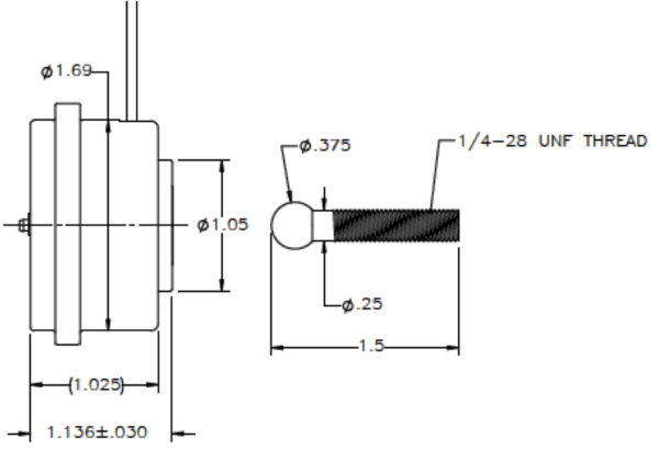
FIGURE 5
(Dimensions of an existing design)
Energy Saving Option
For those who wish not to continuously apply power in order to maintain the locked or unlocked condition (for either a FAIL-SAFE of a FAIL-SECURE format), a Permanent-Magnet can be incorporated into the body of the solenoid.
The attractive “pull-force” that is created by the Permanent-Magnet will hold the solenoid’s internal components in the appropriate position, against the force of an internal spring, thereby maintaining the relevant locked, or unlocked state.
This Permanent-Magnet design requires that only a momentary pulse of energy be applied to the solenoid’s coil in order to actuate the assembly.
Applying a subsequent pulse of reverse polarity to the coil will nullify the hold force of the Permanent-Magnet, allowing the internal spring to return the solenoid’s components to to the position where they will either inhibit, or allow free movement of the Locking-Balls (depending on whether the base design is either FAIL-SAFE or FAIL-SECURE).
The pulses of energy needed to either actuate or deactivate the solenoid can come directly from a small DC power supply, from a battery, or from an appropriately sized capacitor in a capacitive discharge circuit.
NOTE:
When choosing this Energy Saving Option, the device will no longer automatically function in either a FAIL-SAFE, or a FAIL-SECURE mode, because a pulse of energy must be applied to the coil before the system will change state.
This completes the discussion of the Integrated Locking-Receptacle, Ball-Detent Locking Solenoid. If you think that your application could be well served by a FAIL-SAFE, or a FAIL-SECURE version of this device, or of the Independent Locking-Receptacle version that was discussed in part one of this two-part BLOG series, please contact Magnet-Schultz of America. We would be happy to explore whatever is required to meet your system’s locking challenges.
MSA invites you to look forward to future BLOGs concerning evolving BDL-Solenoid technologies.
As a leading manufacturer of standard, specialty and custom Electromagnetic devices—Electromechanical and Electrohydraulic—MSA’s advanced engineering, innovative design and lean manufacturing capabilities enable our customer’s products to outperform their competition. Learn how we can help you with your next project.


Leave A Comment