Magnetic Latching mechanisms fall into one of three distinct categories relative to how they are operated, the electrical energy needed to operate them, and the release force, which their return spring mechanism can generate.
CATEGORY ONE:
Permanent-Magnet/Electro-Magnetic Linear Actuators
(also known as Magnetic-Latching Solenoids or MLS)
A more complete discussion of the differences between Conventional Solenoids and Magnetic Latching Solenoids can be found in the MSA blog titled “Permanent-Magnet/Electro-Magnetic Linear Actuators”.
The design of a Magnetic Latching Solenoid (MLS) is such that when a short pulse of electrical energy is applied to the solenoid coil, sufficient magnetic force is generated to over-come the force of the MLS’ return mechanism (in Figure 1, the return mechanism is a spring). This pulse of energy moves the solenoid’s armature from the “un-actuated” position into the “actuated” position (the “actuated” position is depicted in Figure 1).
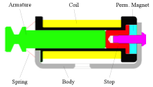
Figure 1: Magnetic Latching Solenoid, depicted in the “actuated” position
Once in the “actuated” position, the permanent magnet that resides inside the MLS will magnetically capture the solenoid’s armature, preventing it from returning to the “un-actuated” position.
When desired, the armature can be released to the “un-actuated” position by passing a small pulse of electrical energy through the solenoid coil, the polarity of which is opposite to that of the permanent magnet. The momentary pulse of this reverse magnetic energy is enough to disturb (nullify) the attractive holding force that the permanent magnet has on the armature, thereby allowing the return mechanism (the spring) to easily move the armature back to its’ original, “un-actuated” position.
The physical size (the size of coil, the size of the permanent magnet, and the size of the solenoid body and armature) of a Magnetic Latching Solenoid is totally dictated by the desired the return spring force. The larger the spring force, the larger all other components must become to achieve the desired operating result. This includes the amount of electrical energy that must be applied to the coil in order to generate sufficient magnetic force to effect “actuation”, and/or to the amount of reverse polarity that is required to nullify the holding force of the permanent magnet.
Typical MLS applications include:
- Medical cabinet, drawer locking solenoids
- Electrical circuit breakers
- Solar power station mirror locking mechanisms
- Electric vehicle charge port door locking mechanisms
One primary advantage of the MLS Technology is energy savings. An MLS device can remain in either the “un-actuated” or in the “actuated” position, without the need for continuously applying electrical power. Such energy savings is particularly valuable in battery-powered scenarios, or in any other scenario, which seeks to conserve energy.
CATEGORY TWO:
Magnetic Latching Mechanisms (MLM)
A Magnetic Latching Mechanism (MLM) can provide extremely high return spring forces, in a much smaller package size than can a Magnetic-Latching Solenoid that has an equivalent return spring force.
MLM mechanisms use the stored energy of their return spring to achieve a high impact, linear motion, while only requiring a short, very low level pulse of electrical energy to effect release of the spring/armature mechanism.
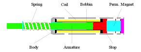
Figure 2: Magnetic-Latch Mechanism (MLM), in the “cocked” position
Unlike the MLS device, which can independently pull the armature into position, the high impact force, small package size of the MLM requires that the armature be manually moved into what is called the “cocked” position.
In this “cocked” position, the return spring remains fully compressed, and the permanent magnet captures and “holds” the armature, thereby storing the compressed spring energy until it is needed.
Although the MLM coil is far too small to enable this style of device to move the armature into the “cocked” position, when energized with just a small pulse of electrical energy, the magnetic field that is generated by the relatively small MLM coil is sufficient to disrupt (nullify) the hold force of the permanent magnet, thereby releasing the spring-loaded armature mechanism.
Once the MLM is manually “cocked”, it can sit forever until the scenario arrives that requires the device to be operated.
The source of the small electrical pulse required to disrupt the permanent magnet hold force can be a battery, or even a capacitive discharge circuit.
Two typical MLM applications include:
- Fire protection system actuators
- Power line interrupter release mechanisms
The primary advantages of MLM devices are:
- Extremely High return spring forces, capable of generating high impact forces,
- Small package size (compared to equivalent the size of Magnetic Latching Solenoids which might be able to provide an equivalent return spring force),
- Extremely low operating current/energy requirements.
CATEGORY THREE:
Permanent Magnet/Electro-Magnets (PM/EM)
A. Conventional Electro-Magnets (EM)
Theory of Operation:
Conventional Electro-Magnets (EM) are simple devices consisting of a wound coil (depicted in Figure 3 by the bobbin and magnet wire), a magnetic structure (depicted in Figure 3 as the steel body), and an armature (also depicted in Figure 3).
Passing electrical energy through the coil generates a magnetic field, which attracts the armature to the EM-Body, hence the term Electro-Magnet. In many applications, the armature is replaced by the structure the mechanical system into which the electro-magnet is mounted.
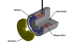
Figure 3: Conventional Electro-Magnet, with Armature
The strength of the magnetic force that is generated by the EM coil is dependent upon several factors:
- The size and the magnetic properties of the EM body,
- The size and the winding design of the EM coil,
- The amount and duration of the electrical energy that is passed through the coil,
- The mechanical and magnetic properties of the armature, and/or the structure of the mechanism which is being attracted by the EM,
- The distance that attracted object is from the EM’s surface, and
- The flatness and surface finish of both the “face” of the EM body, and the object being attracted.
Electro-Magnets are most effective when used to hold an object tightly against the surface of the EM body.
An Electro-Magnet is very ineffective when one tries to use it to attract objects that are even a small distance away from the face of the EM body.
B. Permanent-Magnet/Electro-Magnets (PM/EM)
Theory of Operation:
A Permanent-Magnet/Electro-Magnet (PM/EM) is similar in design to Conventional Electro-Magnets (EM), except for the fact that the PM/EM replaces part of the steel body with a component called the Steel Core, and the PM/EM incorporates a permanent magnet at the base of the steel core (as depicted in Figure 4).
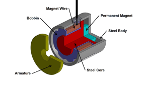
Figure 4: Permanent-Magnet / Electro-Magnet (PM/EM), with Armature
The purpose of adding the permanent magnet is to enable the PM/EM device to hold the attracted object in place, without the need to continuously supply electrical energy to the coil.
As with all Permanent-Magnet/Electro-Magnetic devices, the object that is attracted to the PM/EM can be released by applying a small pulse of electrical energy to the PM/EM coil, the polarity of which is opposite to that of the permanent magnet. This pulse disrupts (nullifies) the magnetic “hold” force of the permanent magnet, thereby allowing the attracted object to move away from the body of the PM/EM.
PM/EM devices find use in applications that require a continuous hold force, without having to continuously apply electrical energy. In this regard, not only does a PM/EM provide energy savings, it can also be utilized as a “Fail-Safe” device. Example:
When used in medical imaging equipment, a PM/EM is typically used to accomplish one or both of the following tasks:
a. The PM/EM is used to lock the imaging target (i.e. a patient bed) in place during the procedure,
b. The PM/EM is used to lock the imaging mechanism (i.e. the X-Ray head) into place during the procedure.
In both scenarios, the PM/EM keeps the relevant item (patient bed and/or imaging head) safely locked into position so that, in the event of a power outage, both the patient and the equipment operator are kept from possible harm due to unexpected movement.
As a leading manufacturer of standard, specialty and custom Electromagnetic devices—Electromechanical and Electrohydraulic—MSA’s advanced engineering, innovative design and lean manufacturing capabilities enable our customer’s products to outperform their competition.
To discover how our magnetic latching expertise can be applied to your next project, Contact MSA Today


Leave A Comment