PART ONE: LINEAR MOTOR THREE PART SERIES
Magnet-Schultz of America (MSA) reviews the concept, genesis of development, background and physical characteristics of a Linear Motor.
Edited by David Stockwell; Technical information provided by Dr. Jonathan Gamble & Kevin Code
INTRODUCTION
In the “old days,” hydraulic valves were manually operated. In the hands of highly skilled operators, precision motion and control of the implements on hydraulic equipment could be achieved with such valves. Starting in the 1980’s, and accelerating through the present day, industrial and mobile hydraulic systems continue to gain increasing levels of complexity and functionality that could no longer be manually controlled by a single operator. The age of electronically operated hydraulic valves, driven by joystick and touch screen enabled interface devices, firmly established its presence on nearly all hydraulically controlled equipment. Slight movements of these joysticks and the resulting proportional response of hydraulic actuators provided a smooth, even flow of hydraulic fluid required to control the equipment’s many hydraulic functions.
The Challenge
As the use of electrohydraulic solenoid actuated valves became more common; space and weight became a premium on the equipment, engendering the next evolution in the hydraulic world, miniaturization and energy conservation.
Even on large equipment, the complexity and proliferation of new implements and functionality created the need for additional hydraulic valves to achieve and to maintain the desired level of performance and control.
Simultaneously, demands arose to reduce the response time, the overall size/weight of sub-systems, and the energy required to operate all of these new functions.
Increased machine capability, coupled with the need for improved efficiency became the major selling points for new equipment. In response, electrohydraulic actuators had to become smaller, faster, more efficient, etc.
Actuator Basics, Unidirectional Actuator Tubes:
Conventional electrohydraulic solenoid actuators generate force in only one direction (providing either a push or a pull function). When mounted on a hydraulic valve, in order to return the valve spool to the un-actuated position, this conventional paradigm demands the use of: 1) an internal or external valve spring, 2) an opposing actuator (mounted on the opposite side of the valve), or 3) a dual length, bi-directional actuator tube, with two coils (one for each direction of movement).
Disadvantages of Unidirectional Actuators, when bi-directional functionality is required:
a. When an opposing actuator is utilized:
The additional tube, coil, and more complex wiring add complexity and cost. On crowded machines, when access to only one side of the valve is possible, field serviceability is compromised.
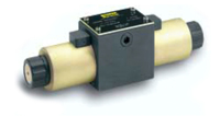
Typical Opposing Unidirectional Actuator Hydraulic Valve Assembly (above)
b. When a Dual Length, Push-Pull actuator approach is utilized:
To help avoid the field service issue described above, manufacturers developed a dual length, dual coil, push-pull style actuator tube. This approach brings the same cost penalty as the opposing actuator approach. The extra tube length also has the disadvantage of increased vulnerability to damage caused by impact.
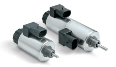
Linear Motor (above left) and Dual Length Push-Pull Actuator (above right)
c. When Cartridge Style Valves are utilized:
Because only one end of a conventional cartridge valve is available for mounting an actuator tube/coil, in order to facilitate bi-directional actuation, a dual length, dual coil, push-pull style actuator tube is required. This approach embodies the same disadvantages as in “b” above.
The Solution
Initial Attempts:
Over the years, a number of bi-directional electromagnetic actuator designs evolved. Very early designs embodied expensive, complex construction to achieve a pressure tight envelope, which could meet 5,000 psi internal pressure rating. Thicker tube walls were explored to achieve higher pressure ratings, but this approach decreased the force, further compromising valve performance.
Later single coil designs overcame the cost and the internal pressure issues, but were still longer than conventional unidirectional actuators, presenting continued dimensional, positioning and damage challenges.
The Next Generation:
To realize true bi-directional actuation, in the same package size as conventional unidirectional coil actuators, and to achieve internal pressure ratings through 6,000 psi., as well as significantly faster response times, Magnet-Schultz of America developed the “Linear Motor.”
Linear Motor Physical Characteristics
Single Coil:
The Linear Motor requires only one coil (to which either positive or negative voltage (polarity) can be applied). This coil is exactly the same coil that is used with MSA’s unidirectional electrohydraulic actuator tubes.
Bi-Directional, Push-Pull, Proportional Motion:
The direction of actuation (the movement of the plunger), and the proportional force which is produced by the Linear Motor are governed by both the magnitude of the current and the polarity of the voltage that is applied to the coil.
Reversing the polarity of the applied voltage changes the direction in which the armature moves. In turn, this reverses both the direction and the force that the plunger imparts to the valve spool.
Size:
All dimensions (length and diameter) of the Linear Motor Tube and Coil are the same as MSM’s unidirectional electrohydraulic actuators.
MSA’s current Linear Motor reference design dimensions include:
• A 19mm diameter Tube mated with a 37mm diameter, 50mm long Coil
• A 22mm diameter Tube mated with a 45mm diameter, 50mm long Coil
Force:
The diameter of the Linear Motor Tube and armature, and the winding characteristics of the coil determine the force characteristics of the actuator.
Interestingly, unlike conventional unidirectional tubes, the force generated by the Linear Motor is largely independent of the armature position inside the tube.
Additional Information About Linear Motor:
If you wish to learn more about Linear Motor’s Design & Manufacturing Techniques, and their Performance & Functional Characteristics, we invite you to read BLOG TWO in this three part series.
BLOG THREE concludes the series with topics covering Linear Motor’s Theory of Operation, Empirical Test Results, and Additional Development Work.
We want to thank you for the time you have invested in learning about Linear Motors, and we encourage you to contact MSA with any questions you may have relating to your electromagnetic actuator needs.

Leave A Comment